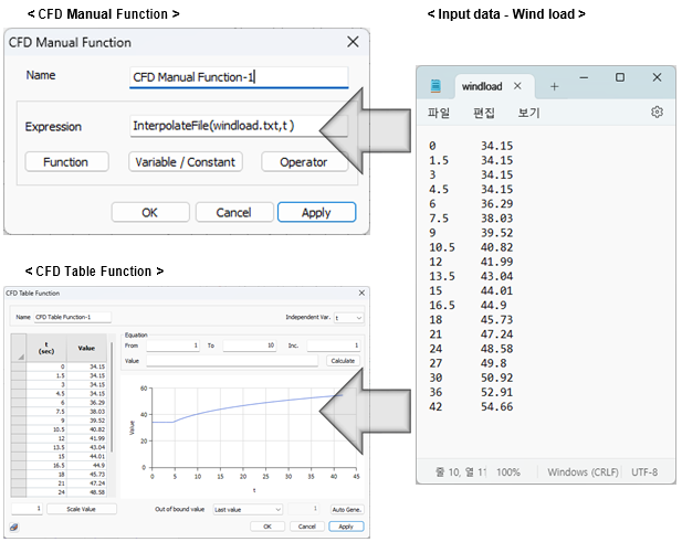

Nuove funzionalità alla CFD table _
In the existing midas NFX, the complex formulas and variables were used to transfer data to the CFD solver and perform analysis with high flexibility. However, as the complexity of the formulas increased, there were difficulties with the Interpolate File function, and it was not possible to verify if it was appropriately reflected.
To address these two drawbacks, we have introduced a new feature called “CFD Table Function” that allows easy application of complex spatial, temporal, temperature, and pressure variables in the form of tables and visually previewed graphs. It is provided in a table format with two columns for variable-value pairs, allowing users to input directly or simply copy and paste external data for convenient application.